
Page 87 - 《含能材料》火工品技术合集 2015~2019
P. 87
792 GUO Fei,LÜ Jun‑jun ,WANG Yao ,FU Qiu‑bo ,HUANG Hui,SHEN Rui‑qi
technology, the integrated circuit technology and tegrated energy conversion unit.
MEMS technology were beneficial to the integrated
and batch manufacturing of the energy conversion 2 Experiment
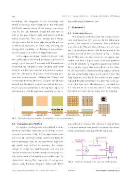
unit. So, the gap between bridge foil and flyer as 2.1 Fabrication Process
well as the gap between flyer and barrel could be We designed and fabricated the energy conver‑
strictly controlled. This could prevent extra energy sion unit based on FPC process. In the fabrication
loss generated due to these gaps during the process process, the material of substrate, flyer and barrel
of electrical explosion of metal foil, reducing the was polyimide (PI), and that of bridge foil was cop‑
driving flyer capability and leading to non‑detona‑ per. The whole processes could be automated in the
tion of explosive or misfire of slapper detonator. production line of FPC, as shown in Fig. 1. Firstly,
In this paper, we utilize Flexible Printing Circuit, the PI film was cut into several 6 cm square sub‑
also called FPC or soft board, to design a structure of strates, and then a 6‑μ m copper film was sputtered
energy conversion unit. Compared with the tradition‑ on the PI substrate by magnetron sputtering method.
al method, we adopted a new substrate and barrel After that, the copper film was etched into the shape
material, and the new manufacturing method can en‑ of a bridge foil by chemical etching means, wherein
sure the consistency of product manufacturing pro‑ the size of the bridge region is 0.5 mm×0.5 mm. The
cess and action process. Utilizing the Voltage and flyer layer was attached to the surface of the copper
current test methods, Photonic Doppler Velocimetry foil, and then the barrel layer was attached to the sur‑
method and D‑optimal method, we studied the elec‑ face of the flyer layer. The diameter of the barrel was
trical explosion performance, driving flyer capability 0.5 mm and its thickness was also 0.5 mm. Finally,
and initiating HNS‑Ⅳ explosive capability of the in‑ the transducer was cut into single units by clipping.
Fig. 1 Fabrication process diagrams of integrated energy conversion unit
2.2 Characterization Method was utilized to measure the velocity history of flyer.
A capacitor discharge unit was utilized to study D‑optimal method was used to evaluate the ability
electrical explosion performance of energy conver‑ of the transformer initiating HNS‑Ⅳ explosive.
sion unit, as shown in Fig. 2. The capacitance value
was 0.22 μF, and high‑voltage switch was three‑di‑
mensional trigger tube. In the experiment, high‑volt‑
age probe was utilized to measure the voltage
change of bridge foil, and Rogowski coil was uti‑
lized to measure the current change of discharge cir‑
cuit, which were all recorded in an oscilloscope. To
characterize driving flyer capability of energy con‑
Fig. 2 Schematic diagram of the capacitor discharge unit
version unit, Photonic Doppler Velocimetry(PDV)
Chinese Journal of Energetic Materials,Vol.26, No.9 , 2018(791-795) 含能材料 www.energetic-materials.org.cn