


2. 96263 Unit of the Second Artillery, Luoyang 471000, China
2. 第二炮兵96263部队, 河南 洛阳 471000
As a new kind of rocket propellant, gelled propellants have advantages for both liquid and solid propellants, including high density, combustion energy, security and long reservation period, etc. However, compared with the traditional liquid propellants, the non-Newtonian character makes the gelled propellants difficult to be atomized. Atomization has attracted widespread and lasting attentions since the beginning of the gel propulsion technology[1-2].
The addition of energetic particles like carbon, aluminum or boron is essential to gelled propellants, and it may significantly increase the energy content per unit volume of the gelled propellant and improve the performance of gelled propulsion system[3-4]. As the addition of energetic particles would alter the rheological properties of gelled propellant[5], some researches have been made to investigate the atomization characteristics of gelled propellants with energetic particles. Jayaprakash et al[6] investigated the injection and atomization characteristics of gelled kerosene with 30%(mass fraction) Al particles, they found that Sauter mean diameter(SMD) of the gel spray was more sensitive to the impingement angle and was dependent on the injection pressure in a highly non-linear manner. Kampen et al[7-8] detail studied the influence of Al particles content of gelled Jet A-1 fuels on rheology, atomization and combustion. The gels prepared in their research appeared "solid" at unstressed ambient conditions and a distinct yield stress occurred. With different generalized Reynolds numbers, different atomization modes were observed. Baek et al[9] investigated the atomization behavior of C934 Carbopol gels with and without 15% SUS304 nanoparticles. They found the nanoparticles decreased the gel strength and made breakup length of gel with nanoparticles remarkably shorter than that of the pure Carbopol gel.
Overall, the mechanics of atomization of gelled propellant with energetic particles are still far from being fully understood in these limited researches. In this work, a new simulant containing carbon particles was prepared and used in atomization experiments. The rheological properties were measured and a series of atomization experiments were made. The linear stability theory was adopted to study the breakup characteristics of the liquid sheet.
2 Experiment 2.1 Preparation of Gelled Propellant SimulantsThe gelled propellant simulant was prepared by dissolving 1%(mass fraction) high-molecular polymer, 5%(mass fraction) carbon particles with an average diameter of about 5 μm in de-ionized water and mixing with an electric mixer for 20 min at 2000 revolutions per minute. This carbon-loaded simulant is named as S1 in this paper. We also prepared another simulant S2 with 99%(mass fraction) de-ionized water and 1%(mass fraction) high-molecular polymer for comparison. The physical and rheological properties of simulants S1 and S2 are similar to gelled propellant: their densities (ρ) are 1010.1 kg·m-3 and 1001.7 kg·m-3, and surface tension coefficients (σ) 0.067 N·m-1 and 0.072 N·m-1, respectively. As the shear rate of the gelled propellant is high in atomization. The rheological properties of the simulants were measured by a rotational rheometer when shear rate and by pipe-flowing experiments when γ≥103 s-1.
The relationship of apparent viscosity (η) and shear rate(γ) can be described by power-law equation, Herschel-Bulkley (HB) equation, Herschel-Bulkley Extended(HBE) equation, etc.[8]. The simulants prepared in this paper appear "syrupy" at unstressed ambient conditions. The experimental results show that the yield stresses (τ0) of the two simulants are very low and both below 10 Pa. Therefore, the yield stress was neglected and the most common power-law equation was adopted.
| $ \eta = K\;{{\dot \gamma }^{n-1}} $ | (1) |
where
η and γ of simulants obtained from experiment and the fitted power-law constitutive curves are given in Fig. 1, and their physical properties are listed in Table 1. From Fig. 1, it can be seen that simulants S1 and S2 are pseudo plastic fluids and their η decrease with the increases of γ. And compared with simulant S2 without carbon particles in Fig. 1, simulant S1 shows higher apparent viscosity under the same shear rate than that of S2. The addition of carbon particles increases the consistency coefficient and decreases the flow index of the simulant, which indicates that the addition of carbon particles evidently changes the physical and rheological properties of the gel. As the de-ionized water is main component of the simulants, the density ρ and surface tension coefficient σ of the two simulants are similar to ones of water (ρ=1000.0 kg·m-3 and σ=0.073 N·m-1), as shown in Table 1.

|
Fig.1 Apparent viscosity and shear rate of gelled propellant simulants |
| Tab.1 Physical property of gelled propellant simulants with and without carbon particles |
Fig. 2 is the schematic diagram of gelled propellant atomization experiment system. At the beginning of the experiment, high pressure gas would be filled into the tank to force the gelled propellant simulant to the jet injector across pipes and values. The impingement angle 2θ and the jet velocity vjet were tuned by adjusting the angle of the doublet injectors and changing the mass flow rate by the control value, respectively. The atomization processes were recorded by a Phantom V12.1 high speed camera with 784×800 image resolution and 5 μs shutter speed. The atomization images were passed to the data acquisition system for further analysis. Meanwhile, important data in the experiment, such as mass flow rate, pressure in the tank, pressure in the injectors, etc. were measured and recorded by the data acquisition system during the whole experiment.

|
Fig.2 Schematic diagram of gelled propellant atomization experiment system |
In order to analyze the atomization characteristics of gelled propellant simulant with carbon particles, 10 atomization experiments were designed with different impingement angles 2θ, jet velocities vjet, injector orifice diameters d and injector orifice length to diameter ratio L/d0, etc., as shown in Table 2.
| Tab.2 Conditions for the atomization experiment |
The generalized Reynolds number(Regen) was used to describe the flow behavior of the power-law fluid, which is defined as ref.[10]:
| $ \mathit{R}{\mathit{e}_{{\rm{gen}}}} = \frac{{{\rho _{\rm{p}}}v_{{\rm{jet}}}^{2-\mathit{n}}d_0^n}}{{K{{\left( {\frac{{3n + 1}}{{4n}}} \right)}^n}{8^{n + 1}}}} $ | (2) |
where ρp is the density of the power-law fluid.
3 Results and Analysis 3.1 Experiment Results and AnalysisIn this paper, the atomization quality is evaluated by the atomization angle (β) and atomization patterns. As we know, when two jets impinge with each other, a fan-shaped liquid sheet forms, and the angle between the left and right rims of the liquid sheet is called atomization angle (β, as shown in Fig. 3). Generally, larger β means better atomization quality. According to former researches[8, 11], with different gels, jet velocities, impingement angles, generalized Reynolds numbers, etc., there are different atomization patterns, including close-rim, open-rim, ligament and fully-developed patterns, etc.[8, 11] The close-rim and open rim patterns indicate poor atomization qualities, while the other two indicate better atomization qualities.
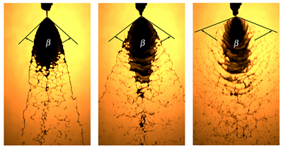
Fig. 3 is atomization images with the impingement angle 2θ=60° and different velocities for cases 1-3. As shown in Fig. 3a, with a low jet velocity (10.2 m·s-1) and Regen, a fan-shaped liquid sheet forms, and it has a distinct rim at the upstream and breakups into ligaments and large drops downstream. The atomization pattern in Fig. 3a is the so-called "open-rim pattern" with the atomization angle β of about 70°. Fig. 3b also shows an open-rim pattern with β=85° under a larger jet velocity (15.68 m·s-1) and Regen=3211. As shown in Fig. 3c, with vjet=22.14 m·s-1 and Regen=3211, the rim of the liquid sheet becomes indistinct, and clearer bow-shaped impact waves occurs and makes the liquid sheet more unstable and breakup into more ligaments and drops. The pattern in Fig. 3c is called "ligament pattern". β in Fig. 3c is about 100°. As discussed in Ref.[8], in cases 1-3, the generalized Reynolds number Regen, which is completely determined by jet velocity, could be adopted as the indication of the atomization quality. Larger Regen(jet velocity) means a larger kinetic energy in jet impingement and would lead to better atomization quality.

|
Fig.3 Atomization images of cases 1-3 |
Fig. 4 shows atomization images with 2θ=90° and different velocities for cases 4-6. Compared with cases 1-3 in Fig. 3, the β in Fig. 4 are larger, which are about 80°, 110°, 140° in Fig. 4a, Fig. 4b, Fig. 4c, respectively. Fig. 4a shows an open-rim pattern, and Fig. 4b and Fig. 4c show ligament patterns. The atomization qualities at impingement angle 2θ=90° are better than ones with 2θ=60° and the similar jet velocities.

|
Fig.4 Atomization images of cases 4-6 |
Fig. 5 shows that the atomization images with ratio of injector orifice length to diameter (L/d0=3.5)under different jet velocities for cases 7 and 8. Compared with case 2 and case 3 with L/d0=8 shown in Fig. 3b and Fig. 3c, there are no obvious differences in Fig. 5. Atomization patterns in Fig. 5a and Fig. 5b are almost identical to patterns in Fig. 3b and Fig. 3c respectively, which indicates that there are no essential differences on the flow characteristics of the jets sprayed from injectors with L/d0=3.5 and 8. As a result, the ratio of injector orifice length to diameter has little influences on the atomization patterns.

|
Fig.5 Atomization images case 7 and case 8 |
Fig. 6 shows atomization images with impingement angle 2θ=60° and different injector orifice diameters for cases 9 and 10. As shown in Fig. 3a (case 1) and Fig. 6, the larger orifice diameters lead to larger mass flow rates and will produce larger liquid sheets. But there are also no essential differences on the atomization patterns of cases 1, 9 and 10, they are all open-rim patterns with almost the same atomization angle about 70°.

|
Fig.6 Atomization images of case 9 and case 10 |
In all the cases studied in this paper, the gelled propellant simulant could hardly to be atomized into fine drops, the main atomization products are ligaments and large drops. Within the investigation conditions, the atomization quality increases with the increase of jet velocity and impingement angle, while the changes of injector length to diameter ratio and the injector orifice diameters influence the atomization patterns little.
3.2 Linear Stability AnalysisLinear stability theory is widely used to evaluate the instabilities of the liquid sheet[12-13]. In this theory, the liquid sheet instability is mainly due to the aerodynamics interactions between the liquid and its surrounding gas. There are two kinds of disturbances that will occur on the liquid sheet: symmetric and anti-symmetric. Squire[14] showed that the anti-symmetric disturbance played a dominant role on breaking the liquid sheet into fragments. Therefore, only the anti-symmetric disturbance is considered here. Schematic of a moving liquid sheet under anti-symmetric disturbance is shown in Fig. 7, a two dimensional liquid sheet moves into a quiescent, inviscid, incompressible gas with velocity Us, the thickness of the liquid sheet is 2hs, the surface tension of liquid is σ, the densities of liquid and gas are ρ1 and ρg respectively, the density ratio of gas and liquid is Rg1=ρg/ρ1. Generally, the wave amplitude on the liquid sheet can be expressed as:
| $ \eta = {\eta _0}\exp [\mathit{i}{\rm{(}}\mathit{kx-}\bar \omega t{\rm{)}}] $ | (3) |

|
Fig.7 Schematic of a moving liquid sheet under anti-symmetric disturbance |
where η is the disturbance wave amplitude, η0 is the initial disturbance wave amplitude, k=2π/λ,
Chojnaki[15] deduced the dispersion relation for a plan liquid sheet based on the power-law constitutive:
| $ \mathit{\Omega }_{\rm{i}}^2 + \frac{{n{{(\mathit{k}{\mathit{h}_{\rm{s}}})}^2}\mathit{\Omega }_i^{2n-1}}}{{\mathit{R}{\mathit{e}_{\rm{s}}}}}2{R_{{\rm{gl}}}}{(\mathit{k}{\mathit{h}_{\rm{s}}})^2}\left( {\frac{1}{{{R_{{\rm{gl}}}}W{e_{\rm{s}}}}}-\frac{1}{{k{h_{\rm{s}}}}}} \right) = 0 $ | (4) |
where Ωi2=ωihs/Us is the non-dimensional disturbance wave grow rate, Res, Wes are the Reynolds number and Weber number of the liquid sheet defined as:
| $ \mathit{R}{\mathit{e}_{\rm{s}}} = \frac{{{\rho _1}U_{\rm{s}}^{2-n}h_s^n}}{K} $ | (5) |
| $ W{e_{\rm{s}}} = \frac{{{\rho _1}U_{\rm{s}}^2h_{\rm{s}}^n}}{\sigma } $ | (6) |
If the liquid sheet breakups when the wave amplitude reaches ηb, the breakup time τb can be obtained as follows:
| $ {\tau _{\rm{b}}} = \ln ({\eta _{\rm{b}}}/{\eta _0})/{\omega _{{i\rm{, max}}}} $ | (7) |
where ωi, max is the maximum grow rate, then the breakup length can be calculated as:
| $ {L_{\rm{b}}} = {U_{\rm{s}}}\ln ({\eta _{\rm{b}}}/{\eta _0}){\omega _{{\rm{i, max}}}} $ | (8) |
Here ln(ηb/η0) is set to be 12 according to Ref. [13].
In this paper, the breakup length of the liquid sheet is defined as the axial distance from the impingement point to the point where the liquid sheet along the axis begins to breakup, as shown in Fig. 8. We assume the liquid sheet speed Us=0.92vjet according to ref. [16]. Solving equation (4) with ρ1=1010.1 kg·m-3, ρg=1.225 kg·m-3, K=16.59 Pa·sn, n=0.29, σ=0.067 N·m-1 and 2hs=2.0×10⁻⁴ m under jet velocity of 10 m·s-1 (cases 1, 4), 15 m·s-1 (cases 2, 5) and 22 m·s-1 (cases 3, 6), the effects of sheet velocity on the stability of the liquid sheet can be obtained, as shown in Fig. 9. It can be seen that the maximum disturbance wave grow rate increases with the increase of the sheet velocity. It means that the liquid sheet will become more unstable at larger sheet velocities, which agrees well with the experiment results of cases 1-3 and cases 4-6 under the same velocities.

|
Fig.8 Definition of the breakup length of the liquid sheet |

|
Fig.9 Influence of sheet velocity Us on the stability of the liquid sheet calculated by linear stability theory |
With equations (4), (7) and (8), the breakup length of the liquid sheet can be predicted. Fig. 10 is the comparison of breakup lengths of liquid sheets predicted by linear stability theory and measured from experiments. As shown in Fig. 10, the variation trend of breakup lengths of liquid sheets calculated from linear stability theory is consistent with the ones measured from experiments. At a low Weber number, the linear stability analysis evidently overestimates the breakup length when compared with the experiment. The relative error between the predicted and measured breakup lengths is about 24% at Wes=128. As the Weber number increases, the relative errors decrease to 14.9% at Wes=618. The errors of the predicted values are considered as a results of neglect of instabilities caused by jet impingement in the linear stability theory.

|
Fig.10 Comparison of breakup lengths of liquid sheets from linear stability analysis and experiments |
(1) The carbon particles increase the consistency coefficient and decrease the flow index of the simulant S1, which makes simulant S1 show high apparent viscosity under the same shear rate.
(2) The simulant S1 can only be atomized into ligaments and large drops. The atomization quality improves with the increases of jet velocity and impingement angles, while the changes in injector length to diameter ratio and the injector orifice diameters show little influences on the atomization patterns.
(3) There are about 14.9%-24% relative errors between the predicted and measured breakup lengths, but the tendency of the breakup lengths predicted by the linear stability theory agrees well with the experiment ones.
| [1] |
Natan B, Rahimi S. The status of gel propellants in year 2000[J]. International Journal of Energetic Materials and Chemical Propulsion, 2002, 5(1-6): 172-192. DOI:10.1615/IntJEnergeticMaterialsChemProp.v5.i1-6 |
| [2] |
LIU Hu, QIANG Hong-fu, WANG Guang. Review on Jet Impingement Atomization on Gelled Propellant[J]. Chinese Journal of Energetic Materials(Hanneng Cailiao), 2015, 23(7): 697-708. |
| [3] |
Hodge K, Crofoot T, Nelson S. Gelled propellants for tactical missile applications. AIAA 99-2976[R], 1999.
|
| [4] |
Haddad A, Natan B, Arieli R. The performance of a boron-loaded gel-fuel ramjet[J]. Progress in Propulsion Physics, 2011, 2: 499-518. |
| [5] |
Wu Zhijian, Hu Lirong. Performance Research of Metallized Gelled Propellant[J]. Missile and Space Vehicle, 2006, 283(03): 52-55. |
| [6] |
Jayaprakash N, Chakravarthy S R. Impingement Atomization of Gelled Fuels. AIAA 2003-316[R], 2003.
|
| [7] |
von Kampen J, Madlener K, Ciezki H K. Characteristic Flow and Spray Properties of Gelled Fuels with Regard to the Impinging Jet Injector Type. AIAA 2006-4573[R], 2006.
|
| [8] |
von Kampen J, Alberio F, Ciezki H K. Spray and combustion characteristics of aluminized gelled fuels with an impinging jet injector[J]. Aerosp Sci Technol, 2007, 11: 77-83. DOI:10.1016/j.ast.2006.08.006 |
| [9] |
Baek G, Kim S, Han J, et al. Atomization characteristics of impinging jets of gel material containing nanoparticles[J]. J Non-Newton Fluid, 2011, 166(21): 1272-1285. |
| [10] |
Metzner A B, Reed C J. Flow of non-Newtonian fluids-correlation of the laminar, transition, and turbulent-flow regions[J]. American Institute of Chemical Engineering Journal, 1955, 4(1): 189-204. |
| [11] |
Fu Q, Yang L, Zhuang F. Effects of Orifice Geometry on Spray Characteristics of Impinging Jet Injectors for Gelled Propellants[R]. AIAA 2013-3704, 2013.
|
| [12] |
Ryan H M, Anderson W E, Pal S, et al. Atomization characteristics of impinging liquid jets[J]. J Propul Power, 1995, 11(1): 135-145. DOI:10.2514/3.23851 |
| [13] |
Dombrowski N, Johns W R. The aerodynamic instability and disintegration of viscous liquid sheets[J]. Chem Eng Sci, 1963, 18(3): 23-214. |
| [14] |
Squire H B. Investigation of the instability of a moving liquid film[J]. British Journal of Applied Physics, 1953, 4: 167-169. DOI:10.1088/0508-3443/4/6/302 |
| [15] |
Chojnacki K T. Atomization and mixing of impinging non-Newtonian jets[D]. Huntsville: University of Alabama-Huntsville, 1997.
|
| [16] |
Heislbetz B, Madlener K, Ciezki H K. Breakup Characteristics of a Newtonian Liquid Sheet formed by a Doublet Impinging Jet Injector. AIAA2007-5694[R], 2007.
|
Atomization characteristics of a gelled propellant simulant with 5% carbon particles with an average diameter of about 5 μm were investigated.